 |
 |
||
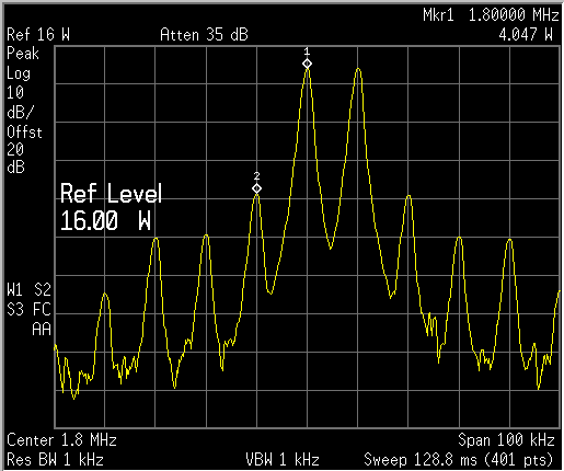
160M IMD, 16W PEP
|
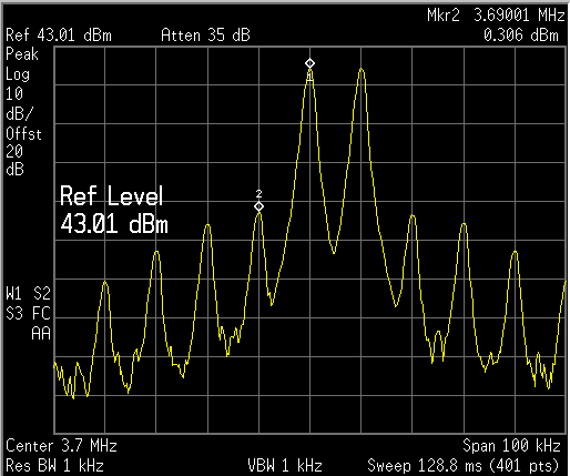
80M IMD, 20W PEP |
|
|
 |
 |
||
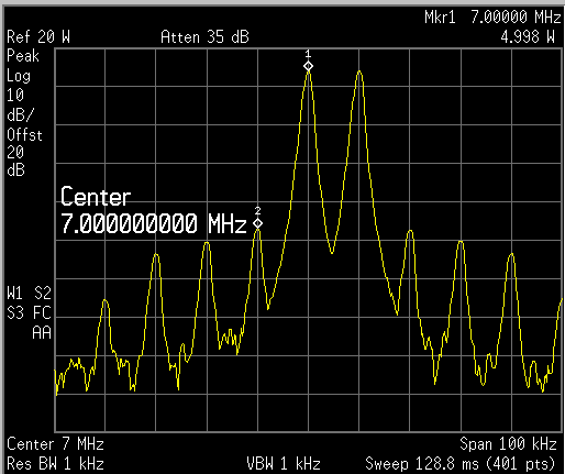
40M IMD, 20W PEP |
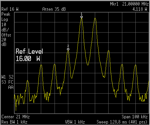
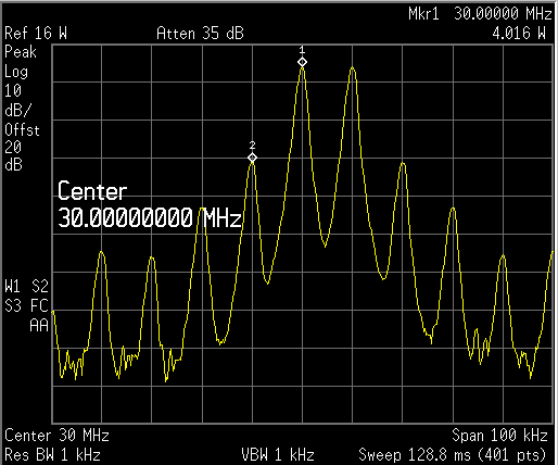
20M IMD, 20W PEP |
||
 |
 |
||
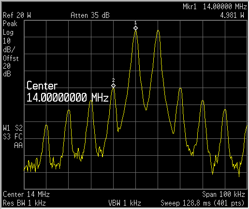
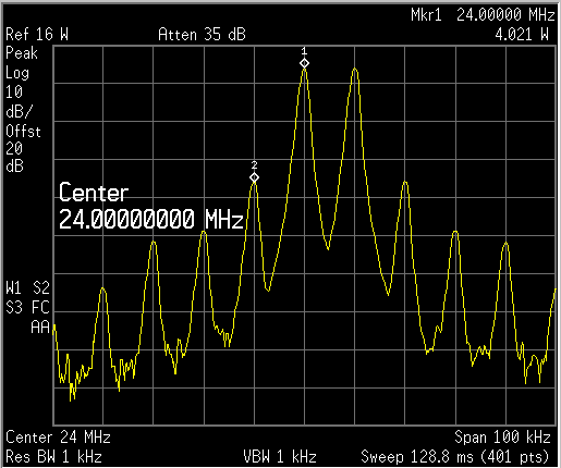
14M IMD, 16W PEP |
12M IMD, 16W PEP |
||
 |
 |
||
10M IMD, 16W PEP |
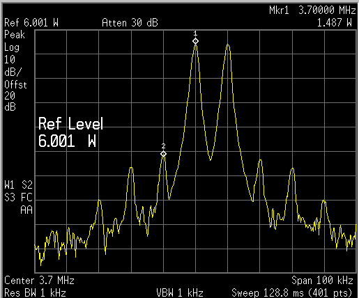
80M IMD, 6W PEP - indication of IMD if used to drive a large FET PA |
||
 |
 |
||
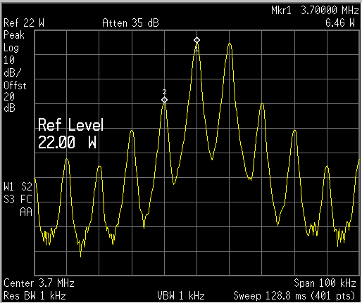
80M IMD, 25W PEP - Note reference level is wrong, should be 25W! |
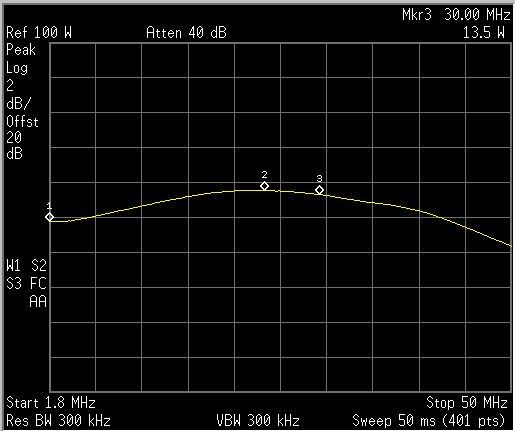
Gain flatness, now better than shown with about 1.5dB mid-band to 1.8MHz and 2.5dB at 50MHz |
||
 |
|||
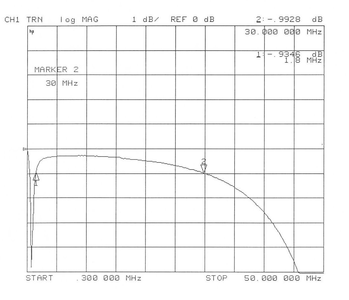
| Effect on received signal through loss with
amplifier being placed "across" signal path. PA causes about 1dB of extra loss at 30MHz. |