Pic-A-Star bandpass filter block
Having built my BPF block using a double sided PCB (I know it should have been
single sided!) I thought a study was required on its performance.
Below are wide and narrow band plots of all the filters, readers may like to
compare the performance with those simulated with Elsie. Elsie is invaluable
for designing and simulating filters, download it here,
download the Pic-A-Star BPF design files here;
note that these use the component values as published with Q of inductors set
at 80 and capacitors set to 1K.
 |
 |
|
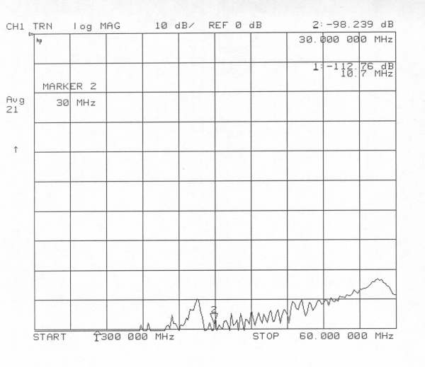
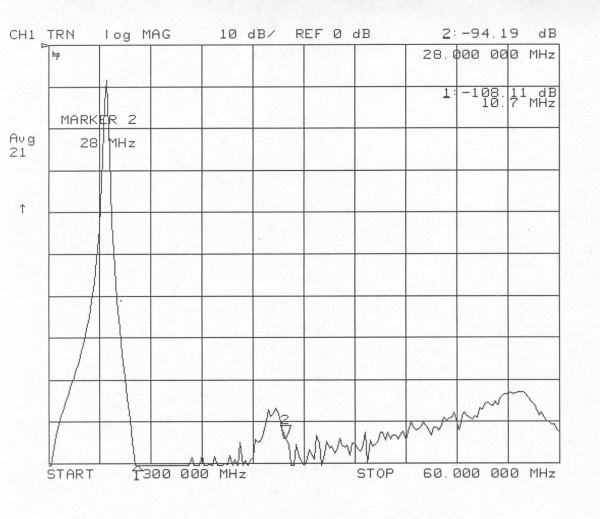
Filter "Blow By", Plot taken by switching on
the unused filter position.
|
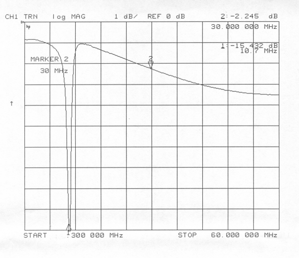
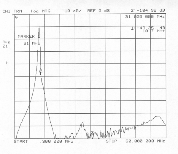
Through loss, note that vertical scale is 1dB/Div, notch
is IF trap. This plot was generated by fitting the spare filter section
with a "straight through" link.
|
 |
 |
|
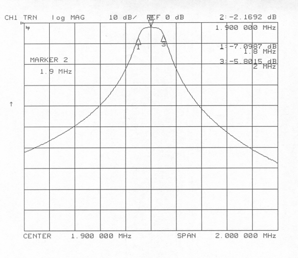
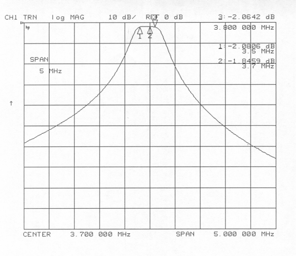
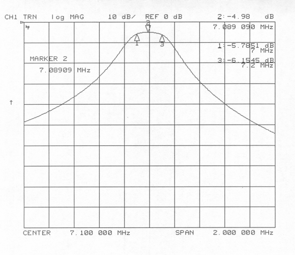
160M narrow band plot.
|
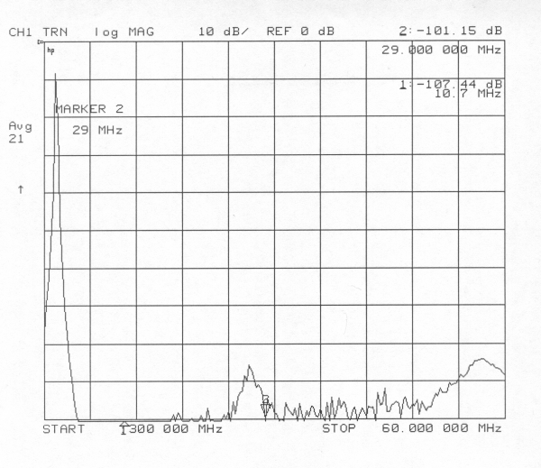
160M wide band plot.
|
 |
 |
|
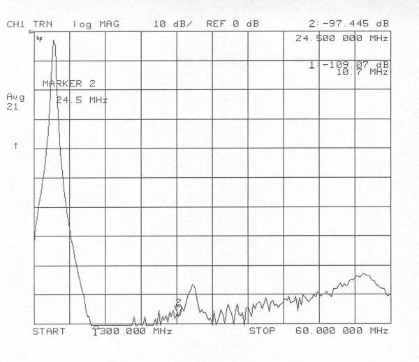
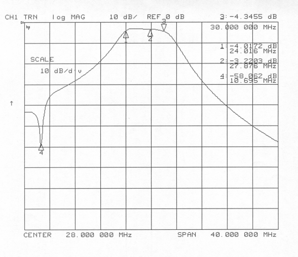
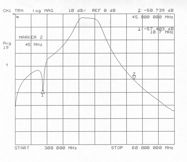
80M narrow band plot.
|
80M wide band plot.
|
 |
 |
|
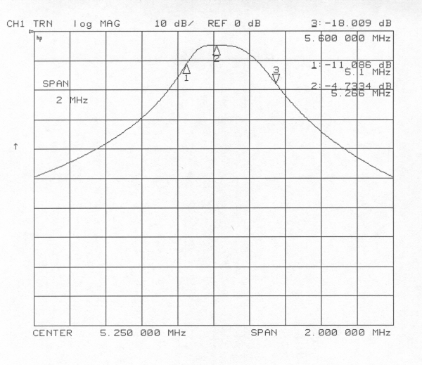
60M narrow band plot.
|
60M wide band plot.
|
 |
 |
|
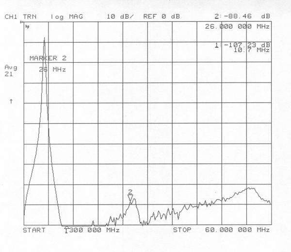
40M narrow band plot.
|
40M wide band plot.
|
 |
 |
|
30M narrow band plot.
|
30M wide band plot.
|
 |
 |
|
|
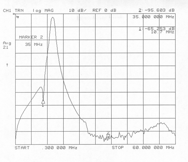
20M wide band plot.
|
 |
 |
|
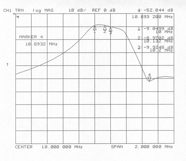
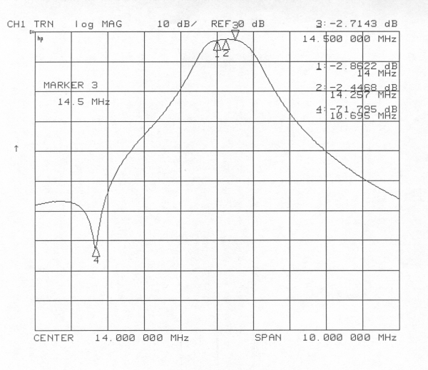
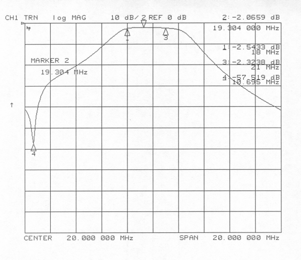
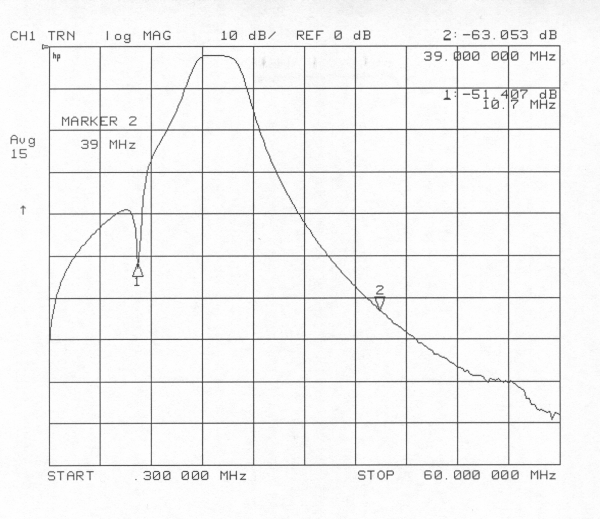
17/15M narrow band plot.
|
17/15M narrow band plot.
|
 |
 |
|
|
|
Conclusion
Although a double-sided PCB was used the stop-band seems good and on the higher
bands matches that predicted by ELSIE.
Through loss is high on the 12/10M filter, previous testing suggests this isn't
caused by the extra capacitance generated by the ground plane, note that the
through loss plot doesn't exhibit a steady roll-off with frequency as you would
expect through shunt capacitance.
