The G4TZR LPF TX/RX switch and attenuator


Photos of a LPF installed in my transceiver

Background

Several amatuers are using the 150W power amplifier and now require a suitably rated LPF, the design shown here was developed by Ray G4TZR. We originally used "standard" circuits given in the Radio Comunications Handbook (RSGB) but found these to be sensitive to component tolerances and winding methods.

Several prototypes were made until the layout presented here produced the performance we required; my expectation was that all harmonics should be at least 60dB below the carrier - this design meets that criteria.

Construction Notes

  1. The number of turns quoted on the schematic are the actual turns found on test with the toroids used during development; since then they have been found to have a higher than normal AL value. Check the wound values against the calculated values on the schematic, we believe that typically 1 turn extra on each toroid will be required.

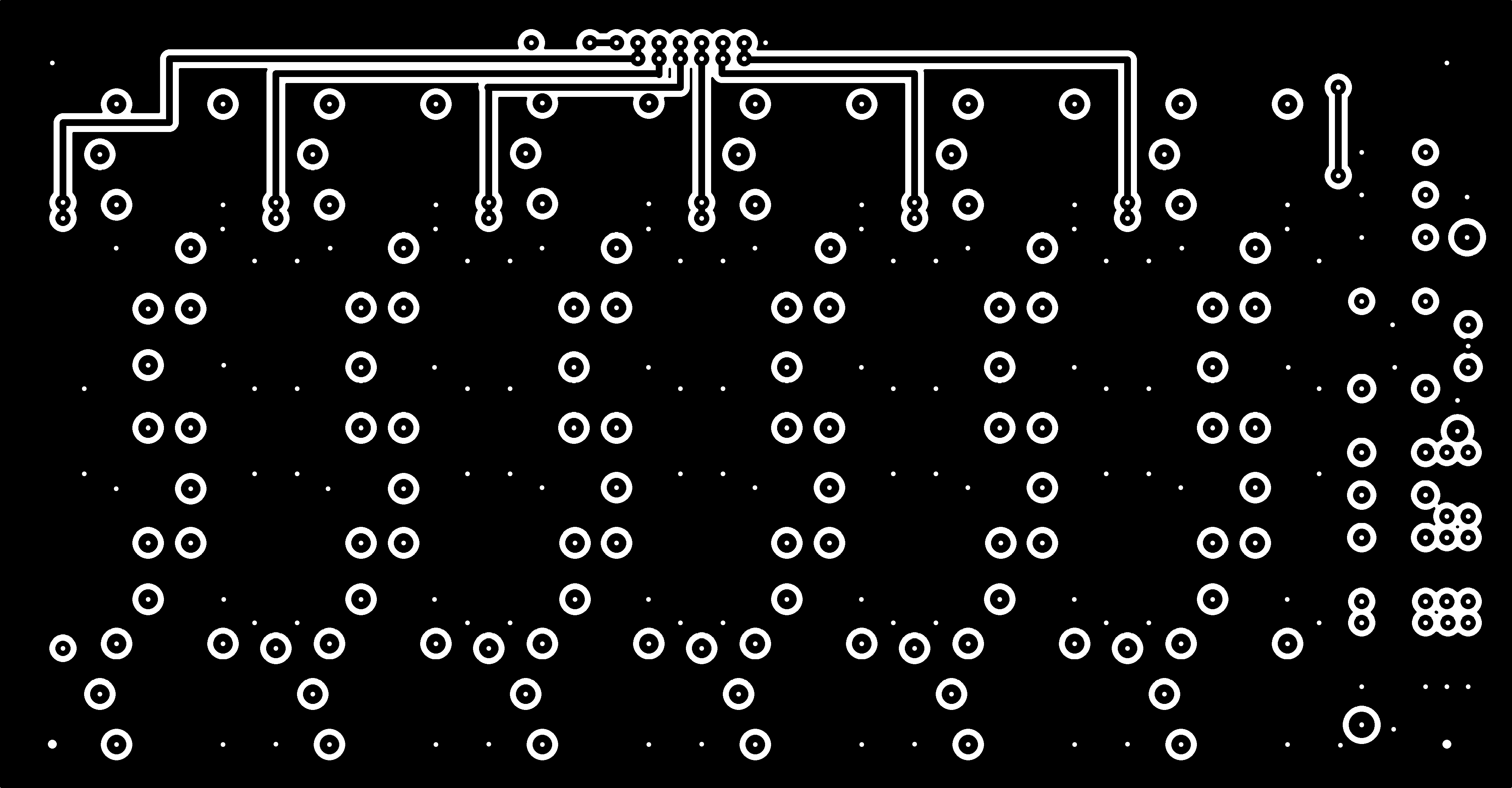
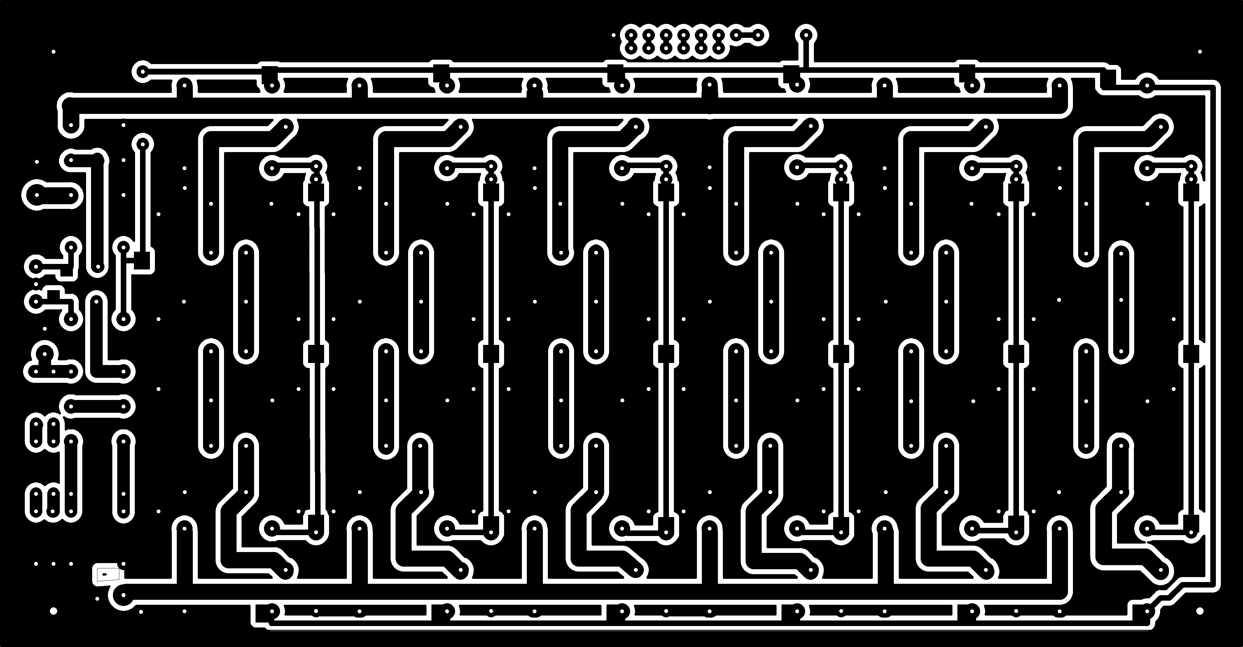
PCB files for board manufacture

Component overlay

Component list

Circuit schematic

Design files

Top side

Bottom side

Overlay


LPF Schematic (drawn by Glenn VK3PE)

Gerber files are not available for this design


Pic A Star builders

Please note that this LPF is NOT specific to the Pic A Star project and can be used in conjunction with any push-pull amplifier, it is NOT suitable for single ended designs.

Steve G6ALU