The 150W bipolar HF power amplifier

Click for large picture

Photos of prototype PA and line up of beta test PAs, note that prototype PA has differences to the final design - no changes have been made since the Beta test

Background

A number of amateurs have purchased SD1487 high power HF transistors from J. Birkett in Lincoln (England), presented here is a development of the Motorola application note AN762 amplifier modified to use these transistors.

Construction Notes

  1. PCBs made from the data provided are likely to made using 1 oz copper substrate, as DC (and RF) currents are very high in places I recomend to fortify the tracks with a trace of tinned copper wire, refer to bottom copper overlay for details.

  2. Q1 and Q2 cutouts can be filed right up to edge of copper.

  3. T3 is made using BN43-402 beads (Fair-Rite part number 2643540402) with 1/4" (6.3mm) outside diameter brass tube threaded down the centre of each bead and solder to each end cheek - note that one end cheek has a break in the track between each tube while the other end cheek has both tubes connected, this end cheek however has a break between the tubes and its connection to the main PCB. Details of end cheeks to follow when time allows.....

  4. The input attenuator has been designed for easily available resistors and isn't a close match to 50R - the output impedance of a driving amplifier won't be either!

  5. The colector pad of TR1 makes direct contact with copper area on top of PCB for heatsinking - refer to Beta test photo, Q3 is sandwiched between PCB and heatsink and its colector pad makes direct contact with heatsink. Yes there is a Q1 and TR1 - my error but too much trouble to change now!

  6. It may be wise to test the bias circuit BEFORE fitting the transistors, fit a 100R resistor from one base to ground as a load and measure the voltage, it should adjust from about 0.4V to 1V, leave at the lowest voltage setting.

  7. Set the bias with the amplifier terminated with a dummy load, I set mine to 300mA total.


PCB files for board manufacture

Component overlay

Component list

Circuit schematic

Design files

Top Copper

Bottom Copper

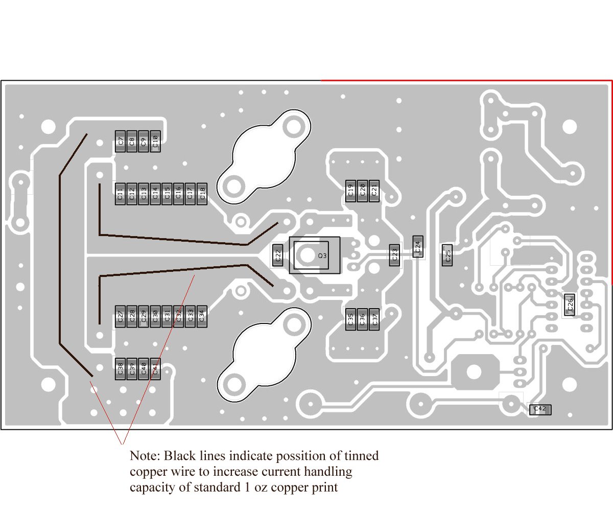
PCB Overlay Top(jpeg)

PCB Overlay Bottom(jpeg)

Component list (PDF file)

Circuit schematic (PDF file)

Files in Gerber and Exellon format for those who wish to make changes. Two versions available, G6ALU and VK3PE - latter are recomended

G6ALU Gerber_Files

VK3PE Gerber Files

Revision history

Date

Item affected

Change

1-03-08 Construction notes line 7. Bias current was shown as 150mA total, from data sheet should be 150mA for each transistor - 300mA total

Suck out

Pic A Star builders

Please note that this amplifier is NOT part of the Pic A Star project - correspondence in relation to this amplifier should not be made via the picastar Yahoo group..

Steve G6ALU