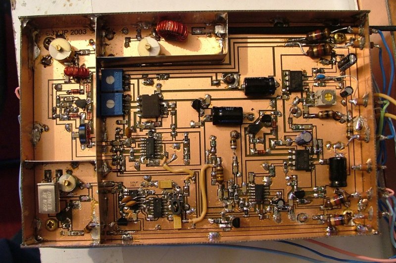
SMD IF Board

Click for large picture of IF assembly

Partially complete IF board

Notes

Differences between this board and the original can easily be identified by components having the suffix "X", these are:

  1. Inclusion of the mixadaptor, this has been added in its entirety.

  2. 2nd oscillator now a colpits circuit to reduce the output level and unwanted radiation from the toroid also easier to adjust and more stable.

  3. Addition of R16X to provide DC bias for an electrect microphone - remove if a standard moving coil type is used.

  4. Inclusion of the 10M4D filter and matching components.

  5. Addition of several de-coupling capacitors for "safety" as the layout has changed slightly.

  6. Microphone gain preset RV5 changed from 47k to 10k so adjustment is more progressive and less "one ended".

  7. There is no longer any provision for "S" meter circuitry as this is now purely digital.

  8. Wide AGC circuitry removed, again this is fully digital.

  9. All modification included (see the official STAR modifications document) except for the preset between C57 and R29, a 15k resistor has been fitted in this position but will need changing to fulfill the setup requirements - refer to set up instructions. I will amend the overlay when time allows to incorporate a preset resistor.

Construction notes

  1. I used low quality screened lead to connect the mix adaptor circuit but miniature coax is advisable.

  2. Off board connections are not shown in the overlay, use the original overlay as positions haven't changed.

  3. Before fitting the Xtal filter make sure the ground plane is relieved where the filter wires pass through.

  4. Screening - it is essential that the oscillator and two filter sections are fully screened, it is also advisable to screen the mix adaptor and advisable to screen the IF sectioncompletely. If an un-screened IF is placed near to the Magic Roundabout then "Fast tuning" spurs will be heard.

  5. As on the original board keep the two 1mH chokes (TX 12v and RX12V) separated to stop power supply oscillation - not as shown on my board above!

  6. Trimmer capacitors on filter input and output are first adjusted for maximum receive (or transmit) signal and then for flatest response.

Notes

PCB files for board manufacture

Component overlay

Component list

Circuit schematic

Design files

This is a development of Peters IF board using surface mount components where applicable. PCB plot SMD IF board overlay

IF board component list Excel

IF board component list Acrobat


Revision history

Date

Item affected

Change

03-01-07 Component list Add C61 & R7 previously marked as not fitted
20-01-07 Component list Add comment "All resistors 1206 package"
  Component list Change R14X to 22K preset resistor
  Construction notes add item 6
13-02-07 Overlay TR1 label corrected to TR1X


Photos to assist with construction:
IF complete
10.7MHz amp section
IF 2nd Osc (10.710MHz)
IF 2nd mixer
Screen lid detail